An opening framework for purpose and promise
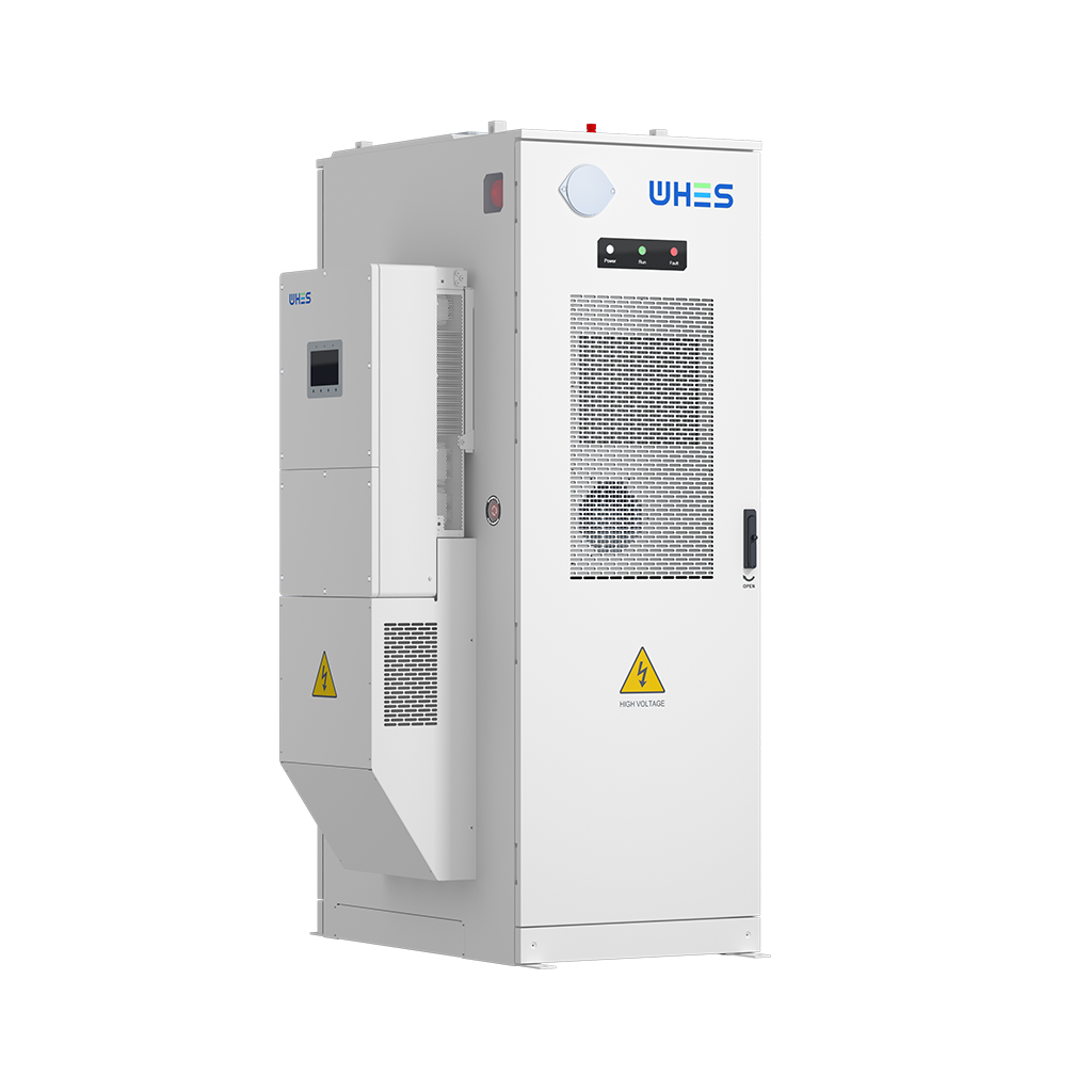
In a world that seeks quiet resilience, co-locating solar arrays with wholesale home battery banks becomes not merely technical work but a deliberate architecture of light and stored time. This framework outlines the modular shafts—electrical, mechanical, and operational—that permit multiple residence-scale batteries to act in concert with a PV array and shared balance-of-system equipment. Early on, ensure your specification references the tested units: an integrated solar battery storage solution can shorten engineering cycles and harmonize inverter and battery management system (BMS) expectations.
Core components and the interfaces that matter
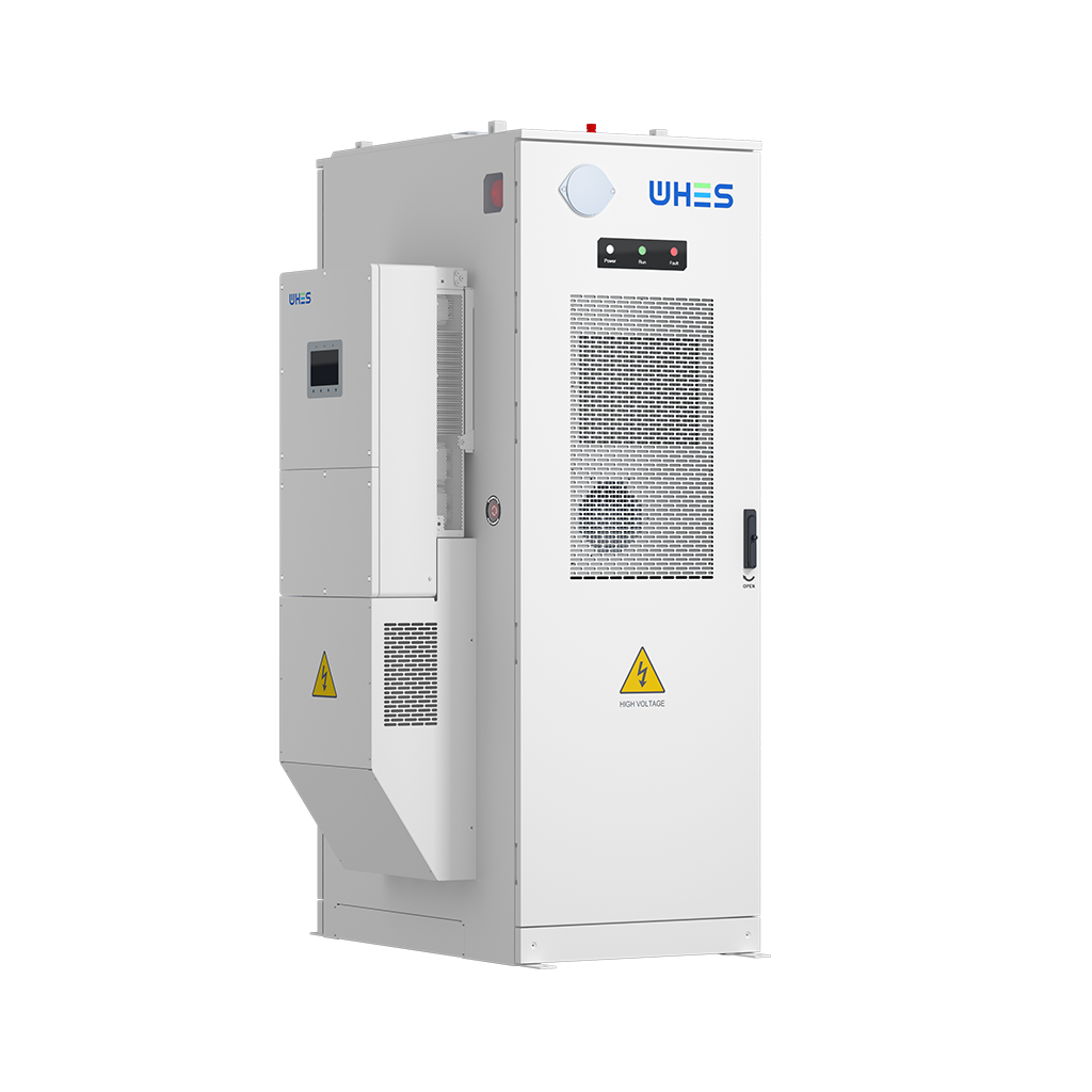
Any co-location project rests on three technical pillars: generation, conversion, and storage control. The PV array supplies DC, inverters perform conversion to AC and handle grid interties, and the battery modules (managed by the BMS) provide dispatchable capacity. Architect these interfaces with explicit standards for nominal voltages, communication protocols (Modbus, CAN), and protective relays. Terms like state of charge (SoC) and depth of discharge (DoD) should be codified in the contract to avoid operational drift. Precision here prevents later disputes about cycle life and warranty triggers.
Site planning, electrical architecture, and distribution topology
Design the distribution topology to minimize point-of-common-coupling conflicts between homes. Consider three common topologies: per-unit AC-coupled systems with a shared microgrid controller; centralized DC distribution feeding multiple inverters; and hybrid clusters where each home retains its own inverter but shares bulk storage. Each topology trades off complexity against efficiency and maintainability. For instance, centralized DC feeders reduce conversion stages but demand tighter thermal and fault management. Lay out cable runs, fault current paths, and protective coordination tables early—these are the drawings that save months on permitting.
Control layers: from local BMS to fleet orchestration
Successful co-location layers local battery control beneath a supervisory energy management system. Local BMS handles cell balancing, temperature limits, and immediate safety interlocks; the supervisory controller aggregates SoC, issues dispatch commands for peak shaving or self-consumption, and adjudicates islanding scenarios. Implement rate-limiters and ramp controls at the inverter to prevent simultaneous inrush events when many units begin discharge. Also build telemetry and remote firmware update channels: they are small investments that yield large operational agility.
Operational strategies and market participation
Decide whether the cluster will optimize for resilience, bill savings, or ancillary revenue. Strategies include time-shift for TOU arbitrage, peak shaving to reduce demand charges, and frequency response where permitted. Each strategy sets different SoC bands and cycling expectations. If pursuing markets, ensure settlement-grade metering and latency-bounded communications. Remember—operational goals dictate battery sizing and inverter oversizing; they are not interchangeable. —
Common pitfalls, mitigations, and procurement notes
Wholesale buyers often stumble on three fronts: ambiguous acceptance criteria, under-specified thermal management, and unrealistic assumptions about interoperability. Avoid these by requiring factory witness tests, specifying cooling duty for worst-case irradiance, and insisting on protocol-level interoperability tests before shipment. Tooling and racking compatibility for clustered installations is commonly overlooked; verify mechanical dimensions, ventilation, and access for maintenance. When in doubt, require a field trial of a representative node prior to full-scale roll-out.
Case example: resilience lessons from islanded systems
When Hurricane Maria struck Puerto Rico in 2017, large swathes of grided infrastructure failed and improvised microgrids became lifelines — a real-world anchor that reminds designers why off-grid capability matters. For communities and developments that must operate autonomously, an off grid battery storage system designed for predictable islanding, black-start sequencing, and prioritized loads can mean the difference between intermittent lighting and continuous essential services. From that lesson: size for critical load duration, test island transition times, and codify black-start sequences into the supervisory controller.

Selection criteria and procurement framework for wholesale buyers
Adopt a scorecard approach: weight technical fit, lifecycle economics, interoperability, and proven field performance. Require vendors to disclose cycle life projections under specified DoD profiles, provide thermal derating curves, and show telemetry schemas. Include acceptance tests that mirror your commissioning procedures to ensure delivered units integrate with your chosen inverter topology and protection settings. Architect contracts to align incentives for uptime and defined performance levels rather than mere shipment milestones.
Advisory close — three golden rules for evaluators
1) Metricize resilience and revenue: demand vendor data on round-trip efficiency, cycle life at project DoD, and mean time between failures; these drive total cost of ownership. 2) Insist on interoperability as a hard requirement: require protocol certification and a witnessed systems integration test that covers islanding, reconnection, and fault scenarios. 3) Prioritize packaged solutions with clear service pathways—field-proven units plus remote diagnostic capability shorten time-to-value.
These rules guide a buyer toward configurations that balance durability with deployability. In practice, the natural solution for many projects is a vendor that combines tested hardware, integrated BMS, and operational services—qualities embodied in partners who think beyond product into system stewardship. WHES. –